
Purpose-built systems.
Specified down to the component.
Explore 50 products and equipment groups across nine categories, including climate controllers, farm-management systems, electrical panels and spare parts. Open each specification to see the application, configuration and engineering considerations.
HT / CATALOG / 03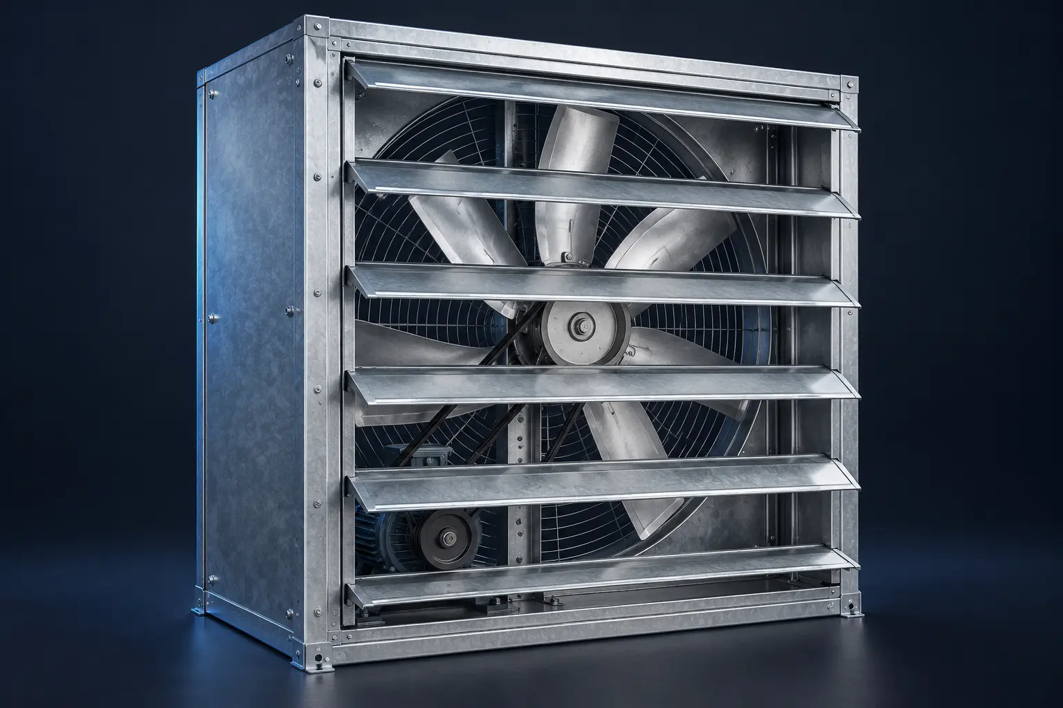
A01 Centrifugal Shutter Exhaust Fans 50-inch / 36-inch · Belt-driven exhaust
Heavy-duty galvanized steel frames house a belt-driven fan and centrifugal airtight louver shutter mechanism. Shutters close when the fan stops to reduce backdrafts and unwanted air leakage.
- Sizes
- 50-inch / 36-inch
- Drive
- Up to 1.5 HP for selected 50-inch models
- Construction
- Galvanized steel frame; centrifugal shutters
- Application
- Tunnel ventilation and negative-pressure sheds
Reference makes: MultiFan (Netherlands), Poosung and Huasheng. Brand availability, origin and approved equivalents are confirmed at quotation; no dealership affiliation is implied.
Specify this equipmentA02 Fiberglass Cone Fans Aerodynamic cone · High-duty ventilation
Aerodynamic fiberglass cones help reduce turbulence and support efficient exhaust airflow. Suitable models can operate continuously during extreme summer heat, subject to motor duty rating and maintenance.
- Housing
- Fiberglass aerodynamic cone
- Use case
- High-demand summer ventilation
- Selection basis
- Required airflow at actual static pressure
- Performance
- Potential airflow improvement up to 10%*
*Comparison depends on the fan, motor, installation and operating pressure. Confirm supplier test data; this is not a guaranteed gain at equal power.
Specify this equipmentA03 Air Inlet Windows Actuated side-wall inlets · Minimum ventilation
Aerodynamic plastic wall flaps connect through steel rods to a central actuator. During winter and brooding, properly adjusted inlets direct cold incoming air toward warm ceiling layers before it reaches birds at floor level.
- Operation
- Motor-actuated flap adjustment
- Linkage
- Steel rods and central drive
- Use case
- Winter and brooding ventilation
- Commissioning
- Pressure, throw and opening calibration
A04 Circulation Fans 18-inch / 24-inch · Internal air mixing
Overhead suspended jet fans positioned along the shed center help mix internal air, reduce heat stratification and eliminate stagnant air zones. Placement is designed around the shed layout.
- Sizes
- 18-inch / 24-inch
- Mounting
- Overhead suspended
- Function
- Internal air mixing
- Application
- Dead-air zones and temperature stratification
A05 Light Traps Light control · Exhaust-mounted modules
Curved black plastic light-trap modules fit compatible exhaust units to limit incoming sunlight and support controlled lighting cycles. Their airflow resistance must be included in fan selection.
- Material
- Curved black plastic baffles
- Mounting
- Compatible exhaust openings
- Function
- Limit sunlight ingress
- Design check
- Pressure drop and remaining airflow
A06 Automated Curtain Dropping Systems Gravity release · Emergency cross-ventilation
PVC backup curtains operate through winches and electromagnetic release clips. A properly configured fail-safe arrangement releases the curtains by gravity on complete utility and generator power failure to enable natural cross-ventilation.
- Curtain
- PVC, winch-operated
- Release
- Electromagnetic fail-safe clips
- Trigger
- Full power / genset failure
- Acceptance test
- Release operation and unobstructed travel
Emergency ventilation must be commissioned and tested regularly. A curtain release system does not replace alarms, backup-power planning or site-specific safety design.
Specify this equipment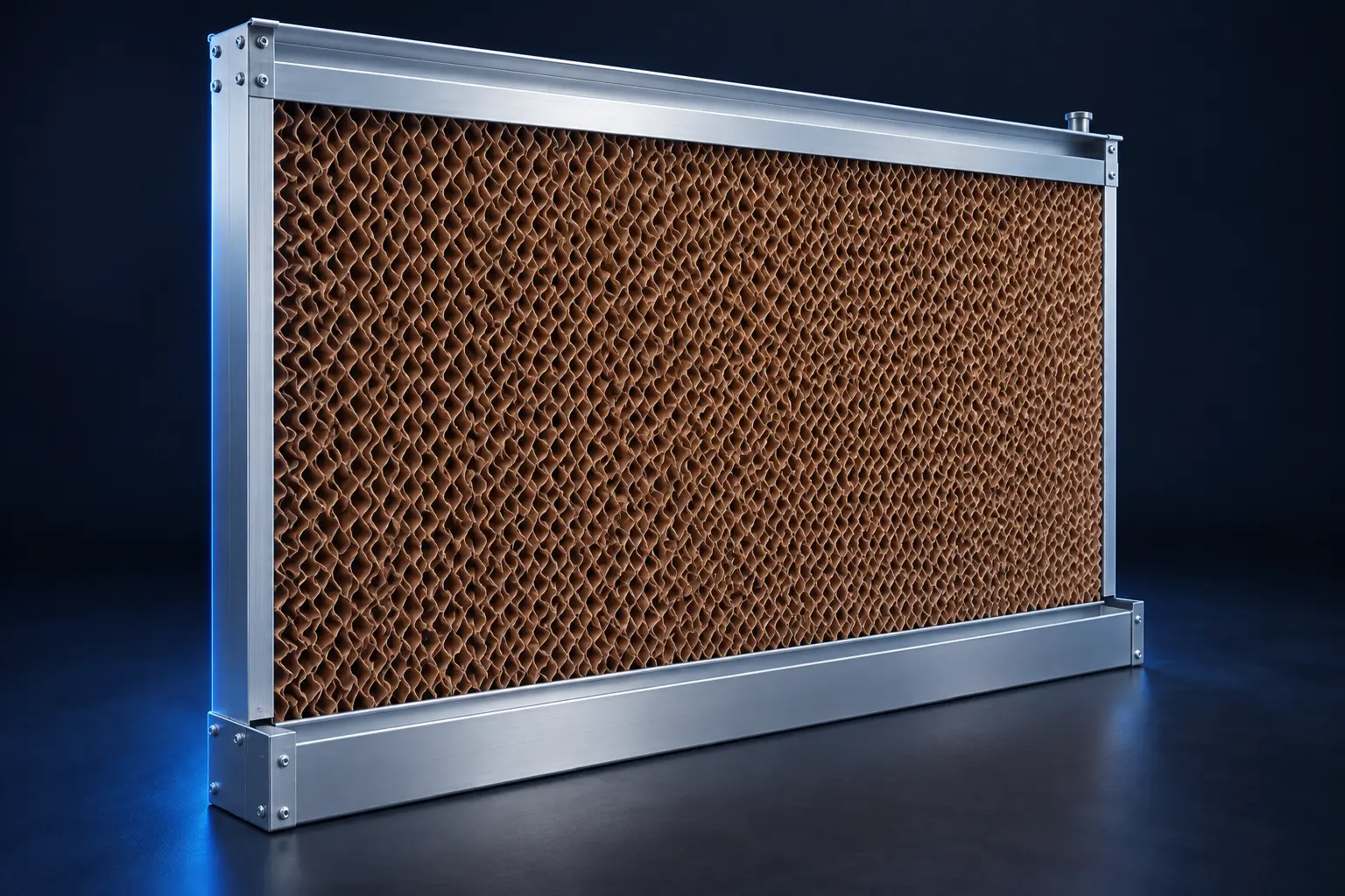
B01 Cellulose Cooling Pads Models 7090 / 5090 · 6-inch thickness
Cross-fluted cellulose paper blocks treated with anti-rot resin provide a wetted surface for evaporative cooling. Performance depends on outdoor dry-bulb and wet-bulb temperatures, airflow and water distribution.
- Models
- 7090 / 5090
- Thickness
- 6 inches
- Material
- Resin-treated cross-fluted cellulose
- Indicative reduction
- 10–12°C in suitable hot, dry conditions*
*Not a guaranteed shed-temperature reduction. High ambient humidity limits evaporative performance; final pad sizing and expected conditions require engineering calculations.
Specify this equipmentB02 Aluminium Framing & Gutters Rust-resistant housing · Water distribution
Extruded aluminium frames support the cooling pads. A perforated top PVC distribution line spreads water across the pad while structural base gutters collect runoff for recirculation.
- Frame
- Extruded aluminium
- Distribution
- Top perforated PVC pipe
- Collection
- Structural base gutters
- Maintenance
- Access for cleaning and water treatment
B03 Water Chiller Units Inline modules · Project-specific cooling
Industrial inline water-cooling modules can be evaluated for selected high-temperature June–August applications requiring controlled pad-water temperature. Chilled water is not automatically an efficient improvement to an evaporative system.
- Configuration
- Inline industrial cooling module
- Use case
- Site-specific summer cooling demand
- Integration
- Pad-water circulation circuit
- Design review
- Heat load, energy use and water conditions
Chiller capacity and economic benefit require a site-specific assessment before inclusion in the system.
Specify this equipment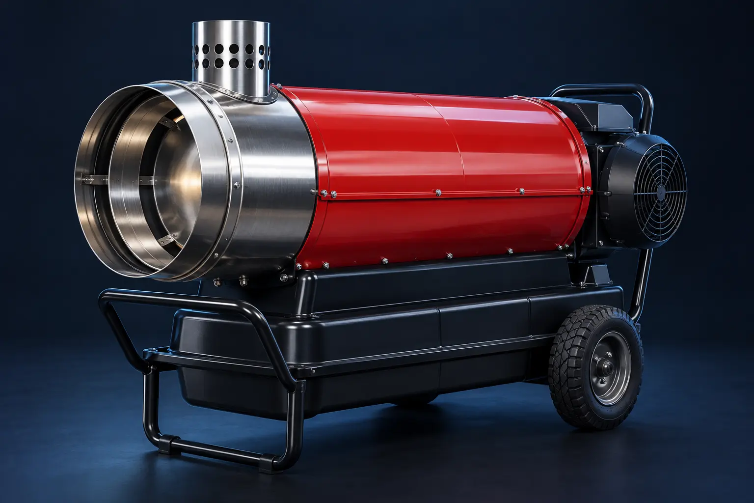
C01 Automatic Forced Air Heaters Electronic ignition · Central control
Central-computer-controlled heaters combine electronic ignition, stainless steel combustion chambers and internal blowers to supply warm air. Burner safety, ventilation and temperature control are integrated during commissioning.
- Control
- Central automation system
- Ignition
- Electronic
- Chamber
- Stainless steel
- Reference equipment
- Holland / Munters-type configurations
Reference makes describe equipment classes only. Supply model, combustion type, fuel compatibility and safety certification are confirmed in the quotation.
Specify this equipmentC02 Biomass / Coal / Wood Fired Furnaces External heat exchange · Ducted warm air
External firebrick furnace chambers transfer heat to a separate clean-air circuit. Ducting distributes warm air into the shed, keeping combustion gases separate from the supplied air when correctly designed and maintained.
- Fuels
- Biomass, coal or wood; model-dependent
- Placement
- External furnace chamber
- Delivery
- Heat exchanger and clean-air ducting
- Assessment
- Fuel availability, emissions and running cost
Potential fuel savings depend on local prices, moisture content, combustion efficiency and maintenance. Savings are not guaranteed.
Specify this equipmentC03 Infrared Ceramic Canopy Brooders Suspended gas brooders · Local radiant heat
Ceramic radiant plates direct localized warmth onto the chick floor zone. Brooder height, coverage and temperature settings are configured to bird age and site requirements.
- Heating mode
- Infrared radiant
- Mounting
- Suspended canopy
- Application
- Localized chick brooding
- Controls
- Fuel regulation and temperature management
C04 Gas Regulators & Plumbing Manifolds Commercial gas distribution · Cylinder-bank integration
Commercial-grade regulators and distribution manifolds connect multiple LPG cylinders to compatible heating equipment. Design includes pressure regulation, isolation and leak-testing requirements.
- Cylinder arrangement
- Multiple 45 kg LPG cylinders, where specified
- Hardware
- Rated regulators and manifolds
- Commissioning
- Pressure and leak testing
- Installation
- Qualified gas-system personnel
Cylinder placement, ventilation and system protection must meet applicable local requirements and the equipment manufacturer’s instructions.
Specify this equipment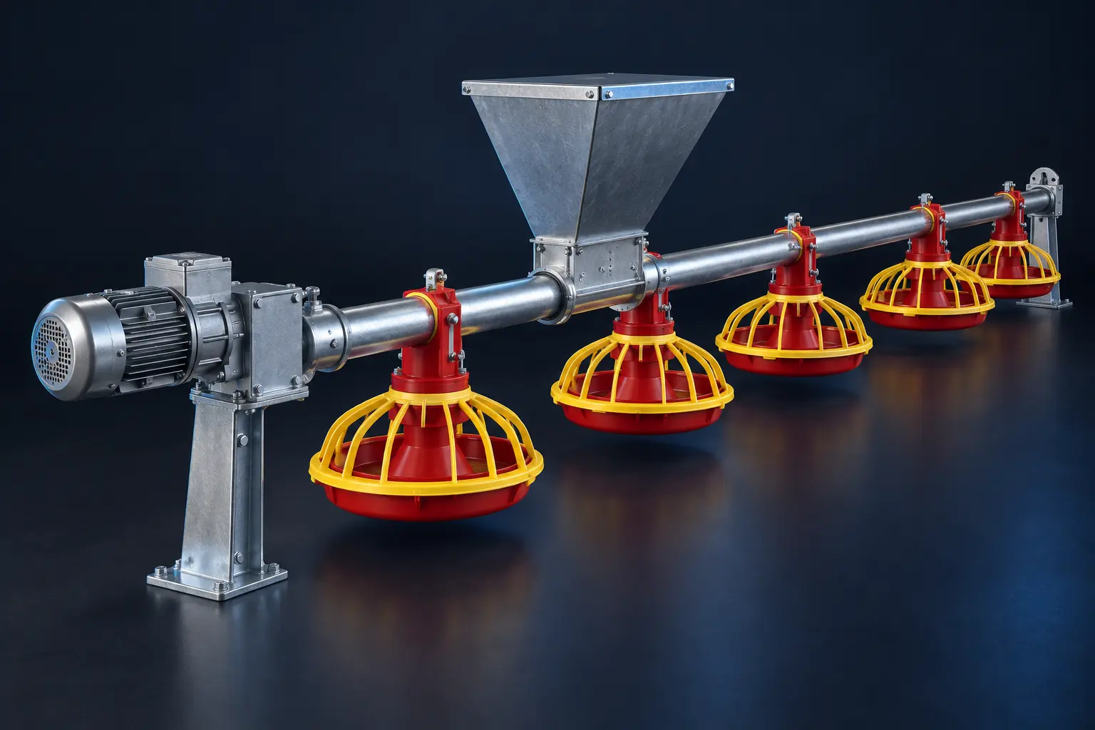
D01 Main Feed Silos & Load Cells 10–30 tonnes · Electronic mass monitoring
Outdoor zinc-coated feed-storage towers stand on an engineered foundation. Electronic load cells at the silo supports measure remaining feed mass after calibration and allow stock monitoring through compatible controls.
- Nominal capacity
- 10–30 tonnes
- Construction
- Zinc-coated steel
- Measurement
- Electronic support-leg load cells
- Civil works
- Engineered concrete foundation
Working capacity depends on feed bulk density; structural loads and calibration are verified for the selected installation.
Specify this equipmentD02 Silo Cross-Auger System 3–4-inch transport tubes · Flexible screw conveyor
Rigid transition tubes with internal flexible steel augers transport feed from the outdoor silo to shed hoppers. Routing and motor sizing account for line length, bends and required delivery rate.
- Tube diameter
- 3–4 inches, selected by throughput
- Transport
- Flexible steel screw auger
- Route
- Outdoor silo to internal hoppers
- Design inputs
- Length, bends and delivery rate
D03 Internal Feed Hoppers & Drive Units 0.75–1.5 HP · High-torque gear motors
Intermediate sheet-metal hoppers supply the feeding line at its head. High-torque geared drives move the line auger and are controlled by the terminal feed-demand sensor.
- Hopper
- Sheet-metal intermediate bin
- Motor range
- 0.75–1.5 HP
- Drive
- High-torque gear motor
- Control
- Demand-based start / stop
D04 Galvanized Feed Pipes & Spirals Continuous feed transport · Internal spiral coil
Connected galvanized pipes carry a rotating internal spiral that moves feed granules along the shed. Pipe alignment, suspension and drive loading are checked during installation.
- Pipe
- Galvanized feed-line sections
- Conveyor
- Rotating internal steel spiral
- Installation
- Aligned suspended lines
- Function
- Feed transport to distributed pans
D05 Broiler Feed Pans Adjustable feed levels · Chick-access and grow-out options
Broiler feed pans provide feed access around the line and allow feed levels to be adjusted as birds grow. Available configurations include adjustable grills, cones, shut-off slides and removable pan bases; the exact arrangement depends on the selected model.
- Adjustment
- Up to 7 levels on selected models
- Components
- Moulded plastic pan, grill, cone and adjustment parts
- Feed control
- Model-dependent adjustment ring and shut-off slide
- Chick access
- Removable-base or floor-level feeding options on compatible models
- Layout
- Pan spacing and birds per pan selected for flock and pan design
- Options
- Fixed or swinging designs and individual pan shut-off, where supported
Pan diameter, grill count, pans per pipe section and bird capacity are confirmed for the supplied model.
Enquire about this productD06 Proximity Switches Capacitive level sensing · Terminal pan control
Capacitive feed-level switches in the terminal pan signal demand to the line drive, automatically starting and stopping feed delivery. Sensitivity and control delays are set during commissioning.
- Sensor
- Capacitive proximity / level switch
- Location
- Terminal feeding pan
- Action
- Automatic drive start / stop
- Setup
- Sensitivity, delay and fail-state checks
D07 Anti-Perch Shockers Purpose-built pulse controllers · Line protection
A thin steel wire above feed pipes discourages birds from roosting on the equipment and contaminating feed. Use a purpose-built, current-limited pulsed anti-perch controller matched to the installation.
- Placement
- Wire above the feed line
- Controller
- Current-limited pulsed energizer
- Purpose
- Discourage roosting and contamination
- Safety
- Manufacturer-approved installation
Do not connect the wire directly to mains electricity. Pulse output and welfare suitability must be confirmed from the selected manufacturer’s specifications.
Specify this equipmentD08 Pan Feeding System Complete feed line · Automatic demand control
An integrated feeding line combines a hopper, delivery pipes, internal auger, feed pans, terminal feed sensor, geared drive motor, suspension hardware and a control box. Feed travels along the line to the pans; the level sensor signals the controller to stop or restart delivery as demand changes.
- Core assembly
- Hopper, delivery pipes, auger and feed pans
- Drive & control
- Gear motor, terminal feed sensor and control box
- Installation
- Suspension hangers and compatible lifting arrangement
- Feeding adjustment
- Pan height and feed level set for bird age and pan model
- Pan options
- Fixed / swinging and individual shut-off, where specified
- Support
- Installation, commissioning, maintenance and compatible spare parts
Line length, pan count, motor rating and lifting loads are designed for the site. Feed-level adjustments and component options vary by the selected pan system.
Enquire about this product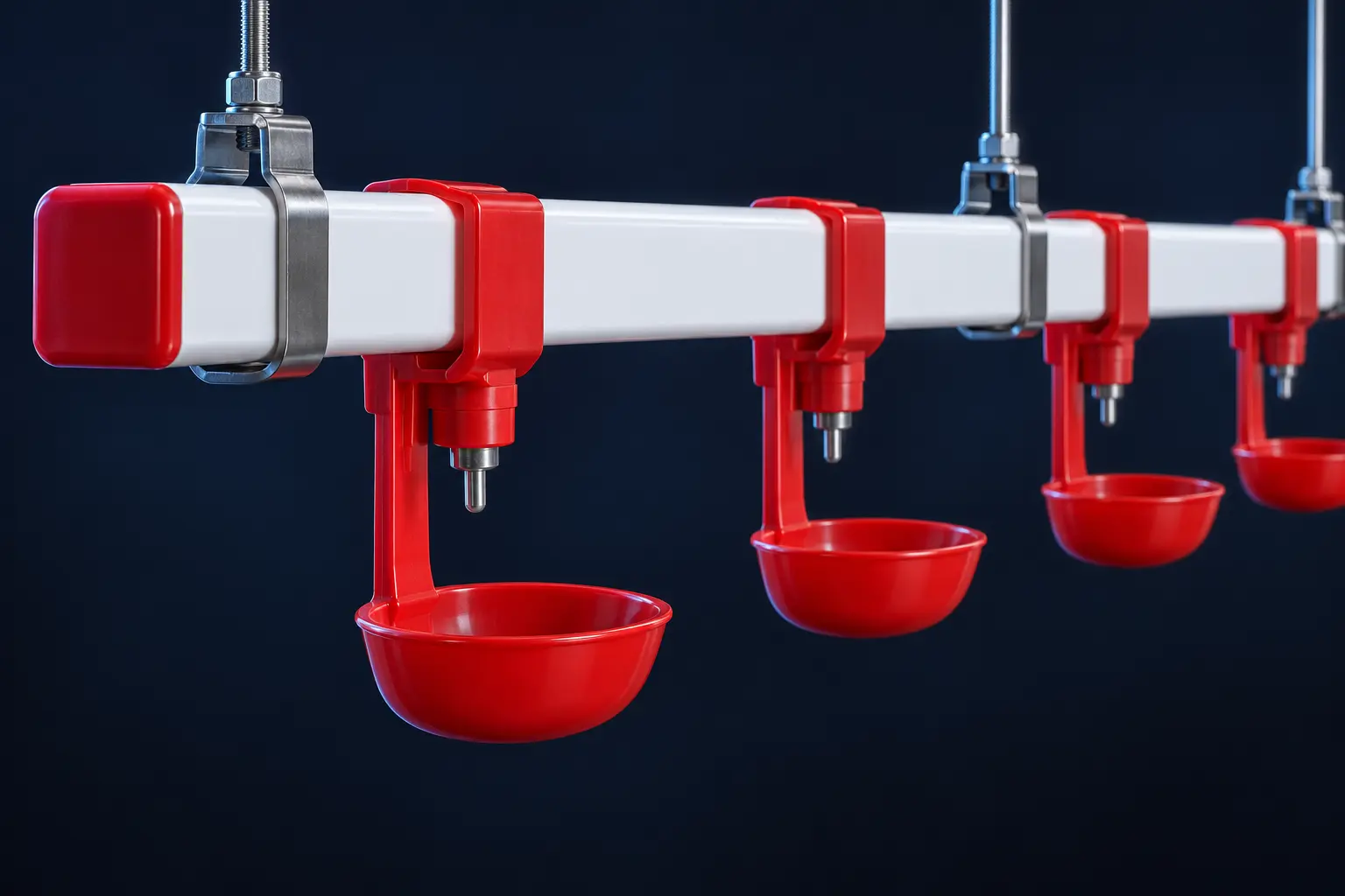
E01 360-Degree & 180-Degree Stainless Steel Nipple Drinkers Precision pins · Age-appropriate water access
Precision-machined stainless steel pins release water when activated. 360-degree nipples allow side and upward activation for young broilers; 180-degree configurations suit selected older-bird and layer-cage installations.
- Pin action
- 360-degree / 180-degree options
- Material
- Precision-machined stainless steel
- Configuration
- Broiler lines or compatible layer cages
- Management
- Correct line height, pressure and flushing
Dry litter depends on pressure, line height, bird behavior and maintenance. Nipple selection alone cannot guarantee dry floors.
Specify this equipmentF01 Main Electrical Panels Incoming supply · Central power control
Custom main panels provide the central point for incoming power isolation, protection, metering and outgoing circuits. The assembly is designed around the site load schedule and approved electrical drawings.
- Scope
- Incoming supply and outgoing feeders
- Components
- Incomer, busbars, metering and protection
- Design inputs
- Voltage, phase, load and fault level
- Configuration
- Site-specific enclosure and circuit layout
F02 Feed Control Panels Feeding-line motors · Demand-based operation
Dedicated feed panels control silo augers, cross-augers and feeding-line gear motors. Automatic demand signals, manual controls and overload protection are configured for the installed feed system.
- Controls
- Manual / automatic operation
- Inputs
- Compatible feed-level sensors
- Motor circuits
- Contactors and overload protection
- Commissioning
- Motor direction, demand signals and interlocks
F03 Emergency Control Panels Alarms · Essential functions · Backup coordination
Emergency control panels bring together the agreed alarm signals, status indication and essential-system controls. The emergency operating sequence is defined for the site and tested during commissioning.
- Scope
- Project-defined emergency functions
- Signals
- Power status and connected alarm inputs
- Integration
- Ventilation or backup controls as specified
- Testing
- Documented functional and fail-state checks
F04 Changeover Panels Utility / generator · Manual or automatic transfer
Changeover panels transfer the site between approved power sources using appropriately interlocked switching. Manual changeover or automatic ATS/AMF arrangements are selected to match the generator and site requirements.
- Sources
- Utility and generator, where specified
- Operation
- Manual changeover or automatic ATS/AMF
- Switching
- Interlocked source selection
- Sizing
- Load current, poles and protection coordination
F05 Distribution Panels Outgoing circuits · Local power distribution
Distribution panels divide the incoming supply into protected outgoing circuits for equipment, shed zones and auxiliary loads. Circuit identification and isolation points support operation and maintenance.
- Circuits
- Equipment, zones and auxiliary loads
- Protection
- Selected for each outgoing circuit
- Documentation
- Circuit labels and load schedule
- Enclosure
- Selected for the installation environment
F06 Lighting Control Panels Scheduled lighting · Compatible dimming controls
Lighting panels coordinate shed or industrial lighting circuits, switching schedules and manual overrides. Dimming is included where compatible drivers, lamps and controllers are specified.
- Functions
- Switching, scheduling and manual override
- Dimming
- Subject to lamp and driver compatibility
- Application
- Poultry sheds and industrial lighting
- Selection
- Connected load and control requirements
Electrical ratings, protection, enclosure, wiring and controls are engineered to the approved project specification. Installation and commissioning require qualified personnel.
G01 Feed Augers & Spiral Coils Flexible augers · Feed transport replacements
Replacement augers and spiral coils for compatible silo-transfer and internal feeding lines. Spiral diameter, winding direction, line length and drive connection must match the existing installation.
- Match
- Pipe and spiral dimensions
- Check
- Winding direction and drive connection
- Use
- Silo transfer or internal feeding lines
- Enquiry details
- Existing model, dimensions and photographs
G02 Replacement Feed Pans & Adjustment Parts Pans · Grills · Cones · Adjustment rings
Replacement feed pans, grills, cones, drop tubes and adjustment rings for compatible broiler feeding lines. Individual parts or complete pan assemblies can be specified to suit the installed system.
- Parts
- Pans, grills, cones and adjustment rings
- Fit
- Model-specific locking and mounting points
- Use
- Worn or damaged feeding stations
- Confirm
- Existing pan model and part dimensions
G03 Feeding Gear Motors & Gearboxes Line drives · Gearboxes · Couplings
Replacement geared motors, gearboxes and compatible drive couplings for feed-line and auger systems. Selection is based on supply, mounting, output speed, torque and duty requirements.
- Match
- Motor voltage, phase and power
- Mechanical fit
- Mounting, shaft and coupling
- Drive selection
- Output speed and required torque
- Information needed
- Motor and gearbox nameplate photographs
G04 Winches & Lifting Assemblies Hand winches · Lifting drives · Line adjustment
Winches and compatible lifting components for raising and lowering feeding or drinking lines. Load capacity, mounting and the complete suspension arrangement are assessed before replacement.
- Use
- Feeding- and drinking-line height adjustment
- Options
- Hand winches or suitable lifting drives
- Match
- Load rating, cable and mounting
- Service
- Inspection, adjustment and replacement
G05 Feed Pipes, Couplers & Drop Outlets Galvanized pipes · Joining hardware · Feed drops
Replacement galvanized feed pipes, couplers, clamps and compatible drop outlets keep feed lines aligned and connected. Outlet spacing and pipe dimensions must match the installed feeding system.
- Parts
- Pipes, couplers, clamps and outlets
- Match
- Pipe diameter and connection style
- Layout
- Outlet spacing and line alignment
- Use
- Section replacement and line repairs
G06 Silo Boots & Feed Hopper Components Transition boots · Hopper outlets · Slide gates
Compatible silo discharge boots, transition components, hopper outlets and slide gates for the feed-transfer path. Selection accounts for the silo or hopper interface and installed auger configuration.
- Parts
- Boots, outlets, transitions and slide gates
- Match
- Silo / hopper connection dimensions
- Interface
- Compatible auger inlet
- Use
- Feed-transfer repairs and component replacement
G07 Feed-Level Sensors & Control Spares Proximity sensors · Relays · Contactors
Compatible feed-level sensors and control components for feed demand and motor switching. Electrical ratings, sensor output type and wiring are checked against the existing control panel.
- Parts
- Level sensors, relays and contactors
- Protection
- Suitable motor overload components
- Match
- Voltage, output type and wiring
- Service
- Fault diagnosis and functional testing
G08 Suspension Cables, Pulleys & Hangers Line suspension · Height adjustment hardware
Replacement suspension wire, pulleys, hangers, clamps and line-support hardware for automated feed and drinking systems. Hardware is selected for the line load and compatible lifting arrangement.
- Parts
- Cables, pulleys, hangers and clamps
- Application
- Feeding and drinking line suspension
- Match
- Load capacity and cable dimensions
- Inspection
- Wear, alignment and secure attachments
G09 Drive Bearings, Bushes & Shaft Couplings Wear parts · Drive alignment · Mechanical repair
Replacement bearings, bushes, seals and shaft couplings for compatible feeding-line drive assemblies. Identifying the original component and checking alignment helps address the cause of repeated wear.
- Parts
- Bearings, bushes, seals and couplings
- Match
- Part number, bore and shaft dimensions
- Service
- Wear inspection and alignment checks
- Selection
- Existing drive make and model
Spare parts are selected for compatibility, not assumed to fit every brand. Share model details, nameplate photographs, dimensions and quantities. Installation, repairs and maintenance can be included in the service scope.
H01 Temp Genesis 1618 Curtain & inlet control · Cold-weather climate management
A multi-function shed controller for coordinating ventilation, curtain and inlet movement, cooling, heating and lighting. Indoor and outdoor measurements support adjustments as weather conditions change.
- Ventilation
- 15-step fan control
- Climate outputs
- 1 cooling system; 2 heater outputs
- Auxiliary outputs
- 1 light output; 1 alarm output
- Temperature sensing
- 4 indoor sensors and 1 outdoor sensor
- Additional sensing
- 1 humidity sensor; 1 pressure sensor
- Connectivity
- Computer-networking upgrade, subject to compatibility
H02 Temp 1400 Minimum ventilation · Step-fan and inverter coordination
Coordinates minimum ventilation with bird-weight targets and the selected maximum operating fan demand. Compatible inverter and step-fan arrangements can be integrated to match the shed ventilation strategy.
- Ventilation
- 10-step fan control; 1 air-inlet control
- Heating / cooling
- 1 heater stage; 1 timed cooling stage
- Lighting / alarms
- Day-length lighting; high/low temperature and humidity alarms
- Sensors
- 3 temperature sensors; 1 humidity sensor
- Display
- 3 display fields for temperature / humidity
- Connectivity
- Computer-networking upgrade, subject to compatibility
Inverter compatibility, control functions and any energy benefit depend on the installed configuration; no energy saving is guaranteed.
Enquire about this productH03 Temp RTron Staged temperature control · Cooling and alarm functions
A climate controller combining temperature stages, timed cooling, heating and lighting with temperature/humidity monitoring. The final sensor arrangement is selected against the model documentation.
- Temperature control
- 12 temperature stages
- Heating / cooling
- 1 heater stage; 2 timed cooling stages
- Lighting
- 1 day-length lighting stage
- Alarms
- High/low temperature and humidity
- Sensors / display
- Humidity sensing; temperature inputs; 3 display fields
- Connectivity
- Computer-networking upgrade, subject to compatibility
Temperature-sensor quantity and the stated 0.5°C performance figure require confirmation against the manufacturer’s datasheet. They are not treated as verified specifications here.
Enquire about this productH04 Temp 2003 Programmable climate control · Curves and data functions
Combines staged ventilation and climate outputs with target curves for temperature, humidity and minimum ventilation. Data logging and loading support configuration review and farm operation.
- Programmable functions
- 8 programmable stages, as listed for the model
- Ventilation
- 10-step fan control, subject to output configuration
- Heating / cooling
- 1 heater stage; 2 timed cooling stages; cooling timer
- Lighting / alarms
- 2 day-length lighting stages; high/low climate alarms
- Sensors / display
- 4 temperature sensors; 1 humidity sensor; 3 display fields
- Management functions
- Temperature, humidity and minimum-ventilation curves; data logger / loader; networking upgrade
Programmable-stage and fan-step counts describe different functions; available simultaneous outputs and the exact model revision must be confirmed.
Enquire about this productH05 Temp 1000 Plus Climate & lighting · Compact staged control
A compact controller for farms needing fan steps, cooling, heating and lighting in one control arrangement, with temperature and humidity displayed for the operator.
- Ventilation
- 5-step fan control
- Climate outputs
- 1 cooling system; 1 heater stage
- Lighting
- 1 light output
- Sensors
- 1 temperature sensor; 1 humidity sensor
- Display
- Temperature and humidity
- Connectivity
- Computer-networking upgrade, subject to compatibility
H06 Temp 100-R5 Fan steps · Timed cooling · Optional humidity sensing
Provides stepped fan control and a cooling timer for straightforward climate-management requirements. Humidity monitoring can be included when the optional sensor is fitted.
- Ventilation
- 4-step fan control
- Cooling
- Cooling-system control and timer
- Temperature sensing
- 1 temperature sensor
- Humidity sensing
- 1 optional humidity sensor
- Display
- Temperature; humidity when equipped
H07 Temp TP80 Minimum ventilation · Variable-speed fan output
Combines a timed minimum-ventilation fan with staged fan control and a 0–10 V variable-speed output. Cooling, heating and alarm functions support routine shed climate management.
- Minimum ventilation
- 1 minimum fan with timer
- Staged ventilation
- 9 fan-control stages
- Variable-speed control
- 0–10 V output for compatible fan controls
- Climate outputs
- Cooling-pump control; 1 heater stage
- Sensors
- 2 temperature sensors; optional humidity sensor
- Alarms
- High/low climate conditions and configured bird-stress alarm
Alarm availability depends on the fitted sensors and model configuration. A bird-stress alarm is a configured warning function, not a direct animal-health measurement.
Enquire about this productH08 Temp TP54 Basic climate control · Expandable monitoring
An entry-level controller for staged temperature control with cooling, heating and an alarm output. Optional humidity sensing and compatible networking can extend the installation.
- Temperature control
- 4 temperature stages
- Climate outputs
- 1 cooling stage; 1 heater stage
- Alarm
- 1 alarm stage
- Temperature sensing
- 1 temperature sensor
- Display
- Temperature / humidity, depending on sensors fitted
- Expansion
- Optional humidity sensor and computer-networking upgrade
H09 Tempo THS100 Temperature & humidity · Storage-room monitoring
A compact temperature-and-humidity unit for applications such as egg-storage rooms and cold storage. Built-in sensing and a digital display provide a local view of environmental conditions.
- Applications
- Egg storage and cold-storage environments
- Temperature sensing
- Built-in temperature sensor
- Humidity sensing
- Built-in humidity sensor
- Readout
- Digital temperature and humidity display
- Control integration
- Confirm output type, range and switching capability before selection
The operating range and environmental rating must suit the storage conditions; sensing capability alone does not establish refrigeration-control compatibility.
Enquire about this productModel names identify products available for supply and integration; they do not imply manufacture by Horizon or an authorized dealership. Current availability, hardware revision, included sensors and final specifications are confirmed in the quotation.
I01 Farm Management System Central farm monitoring · Computer-based control
Central software collects climate information from compatible controllers and presents it at a farm-management computer. Supported configurations allow operators to review readings, adjust target temperatures and permitted settings, and receive controller alarm notifications.
- Platform
- Windows-based software; supported versions to be confirmed
- Functions
- Climate-data collection and central monitoring
- Operator control
- Remote setting changes on compatible controllers
- Alarms
- Controller-event notification at the management computer
- Requirements
- Compatible software, controller firmware and communication interface
Computer monitoring does not replace the on-site alarm or fail-safe controls. Licensing, operating-system support, remote-access method and available functions are confirmed for the supplied configuration.
Enquire about this productI02 Master Link Controller-to-PC interface · Multi-controller farms
A communication interface connecting compatible climate controllers to a central farm-management computer. The supplied configuration can support multiple controllers on one communication network.
- Role
- Communication between climate controllers and a PC
- Listed capacity
- Up to 60 compatible controllers per interface
- Traffic
- Controller readings and supported command exchange
- Selection checks
- Controller models, cabling, distance and software compatibility
The listed connection limit is subject to the interface version, network layout and approved controller combination.
Enquire about this productI03 Mini Master Link USB interface · Smaller controller networks
A USB communication interface for compatible farms with a smaller number of climate controllers. It links the farm computer to the supported controller network for monitoring and permitted setting changes.
- Computer interface
- USB
- Application
- Smaller compatible controller networks
- Requirements
- Supported drivers and farm-management software
- Capacity
- Confirm controller count and communication distance
I04 Temp AL 01 Alarm monitoring · Rechargeable battery backup
An alarm unit for connected fault signals such as power loss, fan overload or out-of-range environmental readings. Compatible feed and water monitoring equipment can provide additional alerts when those inputs are supported.
- Backup
- Rechargeable battery backup
- Potential signals
- Power failure, fan overload and high/low temperature
- Additional signals
- Feed / water deviations with compatible monitoring inputs
- Input arrangement
- Input quantity and supported signal types to be confirmed
- Commissioning
- Alarm trigger, battery condition and backup operation tests
Confirm supported input quantity, signal types and alarm-output behavior against the selected unit before ordering.
Enquire about this productModel names identify products available for supply and integration; they do not imply manufacture by Horizon or an authorized dealership. Current availability, hardware revision, included sensors and final specifications are confirmed in the quotation.
Specification guide, not a binding datasheet. Final makes, dimensions, ratings, capacities, availability and performance are subject to site assessment and the approved quotation. All equipment imagery is AI-generated and illustrative.
Let’s engineer your next project.
One team. From the first specification to the final commissioning.